Using ALSA for steady and precise oscillation control
2021, July 29 (Thursday)
Over this summer at Wesleyan University, I’ve been working in the Ellis lab on some physics research, specifically regarding the instrumentation by which we can control oscillations. Recently, I presented a poster session on my work, titled “towards software-based methods for steady and precise oscillation control at kilohertz frequencies.”
Overview
The gist of the work is this: our lab wants to study a variety of non-Hermitian oscillators, which of course have natural losses in them. We would like to use a feedback loop to cancel out these losses (and perhaps do other things!) so that the oscillations are effectively undamped. So far, I’ve worked mostly on a bar of aluminium with four piezoelectric transducers affixed, which allows us to both read displacements and apply forces in both x and y directions. My abstract is below:
The Ellis lab investigates a variety of non-Hermitian systems where active manipulation of the equations of motion can be used to engineer novel behavior. The instrumentation behind such manipulation and study of high-frequency oscillators is the focus of this research; we assess the efficacy of using a Raspberry Pi with external audio card connected to piezoelectric transducers to serve as a low-cost, easily reproducible, and versatile feedback loop. By developing our own software to interface with the Advanced Linux Sound Architecture, we apply our inexpensive hardware to sustain an effectively undamped gyration of an aluminium bar at 7 kHz for many thousands of cycles. Features of our implementation include a matrix of finely adjustable gain parameters, recursive linear filtering to provide sub-sample control over phase shift and potential band-pass filtering, and concurrent data acquisition from two channels without interrupting the feedback loop. Overall, we demonstrate that software-based oscillation control strategies are feasible and effective at kilohertz frequencies without the need for costly hardware.
Mathematical description
Defining, for example, a gain parameter \(G_{xy}\) to represent the force applied in the x direction per unit of displacement in y, as well as k and b to represent spring and drag constants respectively, we can set up Newton’s second law as a matrix relation:
\[\pmb{r} = \begin{bmatrix} x \\ y \end{bmatrix} \hspace{0.5em} \mathbf0 = -m\ddot{\pmb{r}} - b\dot{\pmb{r}} + \begin{bmatrix} -k & G_{xy} \\ G_{yx} & -k \end {bmatrix} \pmb{r}\]With an ansatz for \(\pmb{r}\):
\[\text{let}\;\; \pmb{r} = \pmb{r}_0 e^{iωt} \;\Rightarrow\; \dot{\pmb{r}} = iω \pmb{r} \;\Rightarrow\; \ddot{\pmb{r}} = -ω^2 \pmb{r} \\\] \[\mathbf0 = mω^2\pmb{r} - ibω\pmb{r} + \begin{bmatrix} -k & G_{xy} \\ G_{yx} & -k \end {bmatrix} \pmb{r}\] \[\mathbf0 = \begin{bmatrix} mω^2 - ibω - k & G_{xy} \\ G_{yx} & mω^2 - ibω - k \end {bmatrix} \pmb{r}\] \[\therefore\hspace{0.5em} mω^2 - ibω - k = ± \sqrt{G_{xy} G_{yx}}\]When we solve the quadratic above, our solution for the complex angular frequency can be expressed in terms of the natural frequency \(ω_0\) as:
\[ω = \frac{ib}{2m} ± ω_0 \sqrt{1 - \frac{b^2}{4mk} ± \frac{\sqrt{G_{xy}G_{yx}}}{k} }\]What’s interesting about this is that it shows we have quite a bit of control over the complex frequency by only controlling the two cross-axis gain parameters (not to mention adjusting the k for each axis). In fact, it’s possible to choose parameters such that ω becomes completely real for one rotation direction, but with a positive imaginary component for the other rotation direction. This creates a handedness to the oscillation! A real frequency implies undamped rotation, whereas a positive imaginary component creates exponential decay. This is why when we tune our gain parameters, the oscillation will maintain a consistent rotational direction in its normal mode.
One more thing to keep in mind—circular oscillation is not the only option, as our system can also form a standing wave (e.g. the line \(y = x\)). Using the matrix from above, we can solve:
\[(mω^2 - ibω - k)x = G_{xy} y \hspace{0.5em}\Rightarrow\hspace{0.5em} \sqrt{G_{xy}G_{yx}}x = G_{xy} y\]From this we know that if the product of the two gains is negative, then x and y will be 90° apart (since the square root will be imaginary), whereas if the product of the two gains is positive, then they will be either in phase or 180° out of phase. The former case is a circular mode—which we are particularly interested in—and the latter case is a standing wave.
Oscillator and Pi setup
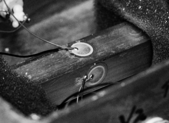
The oscillator is an aluminium bar with approximate dimensions of 12.8 mm × 12.8 mm × 100 mm. Four piezoelectric transducers are attached along the midsection of the bar, such that both x and y axes have both a pickup and a drive transducer, respectively. A close-up of the transducers affixed to the bar:

Not much was done to the Raspberry Pi other than some simple performance and configuration tweaks, such as:
- installing the
PREEMPT_RTLinux kernel patch from here, - using raspi-config to boot into console instead of spinning up a window manager,
- editing /boot/cmdline.txt to set
isolcpus=3(so we have CPU3 all to ourselves), - setting the scaling governor for each CPU core to “performance,” and
- editing /etc/asound.conf to set our sound card as default.
The specific models of hardware we used were the Raspberry Pi 4B and the HiFiBerry DAC+ ADC Pro. This means that one could reproduce this setup to study oscillations at 192 kHz sample rates for only a little over 100 USD.
The code
The code for this project is hosted at this git repository. I was
surprised at how fast it can be to read, manipulate, and write two channels of
192 kHz audio in ALSA! Initially, I used regular old alsaloop in combination
with jackd, which allowed me to change the period size (thus latency, thus
phase shift) on the fly. However, the resolution of phase shift achievable from
this is only around 13°, which is pretty terrible for our purposes. Thus we
decided I would have to do it all myself, so that phase shift via interpolation
would be possible.
Some cool features include:
- independent linear recursive filters for both channels,
- ability to set feedback parameters on the fly,
- ability to record data while simultaneously operating feedback, and
- a simple Python API!
Results
I used the following Python code to test the oscillation:
import time
import qlab_alsaloop

feedback = qlab_alsaloop.Feedback()

feedback.set_psize(256)
feedback.set_gain(0, 0.25, 0.25, 0)
feedback.set_filter(1, 0, 0, 1, 0, 0)
feedback.send_parameters()
time.sleep(2)
feedback.tune_coarse_phase()

time.sleep(2)
feedback.tune_fine_phase()
time.sleep(2)

# coarse adjustment to gains
feedback.start_hold_amp(3)
time.sleep(20)
feedback.stop_hold_amp()

# fine adjustment to gains
feedback.start_hold_amp(3, tolerance=0.02, gain_step=0.001)
time.sleep(10)
feedback.stop_hold_amp()

# record data!
frames = feedback.get_frames(8192)
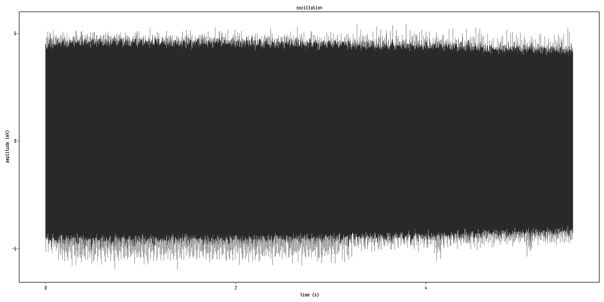
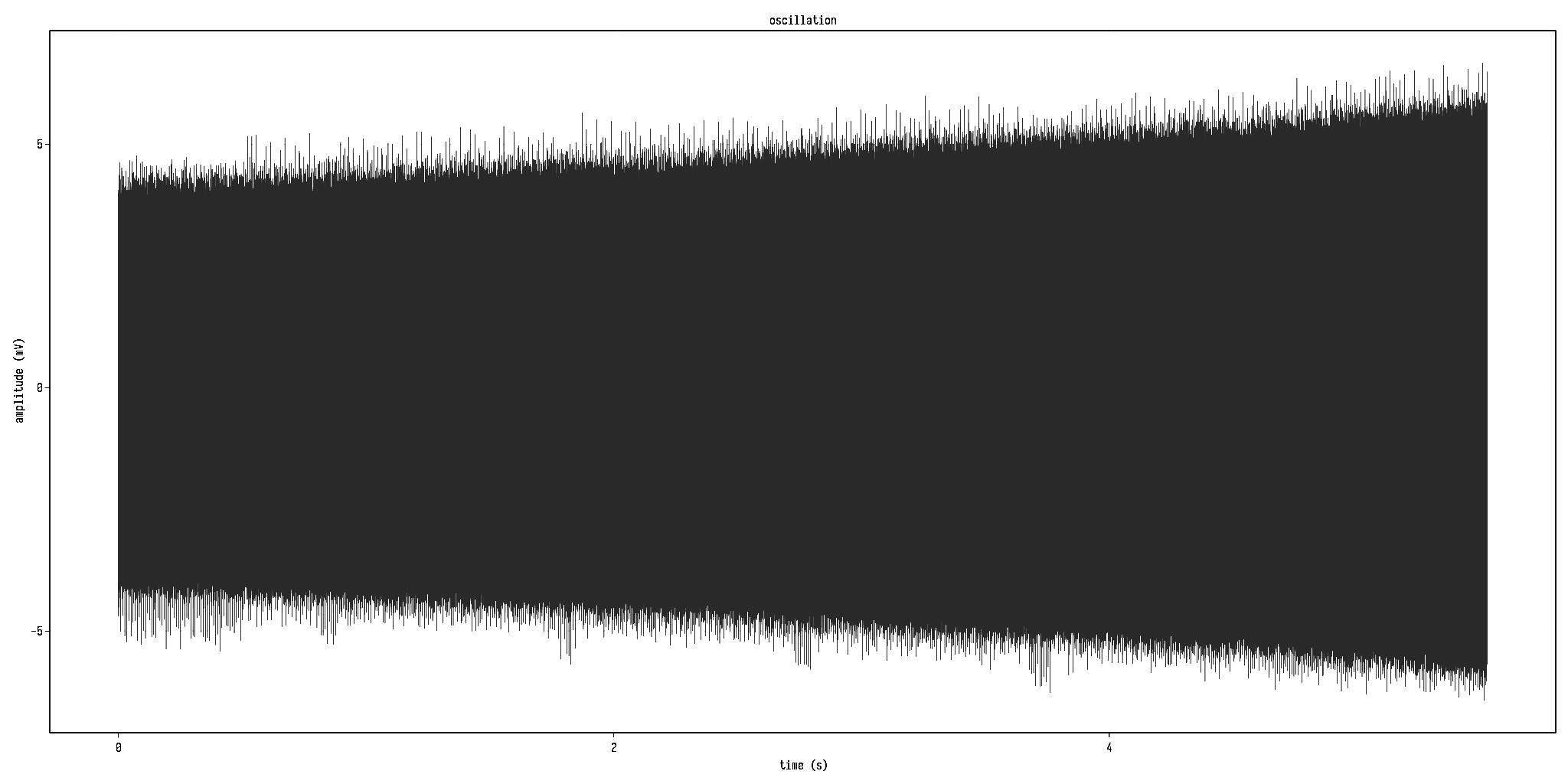
First of all, the amplitude-holding is relatively stable. Below are two graphs of the oscillation with only primary feedback operating, showing either decay or growth due to slight imbalances in gain and loss. Note that the half-life is on the order of seconds!


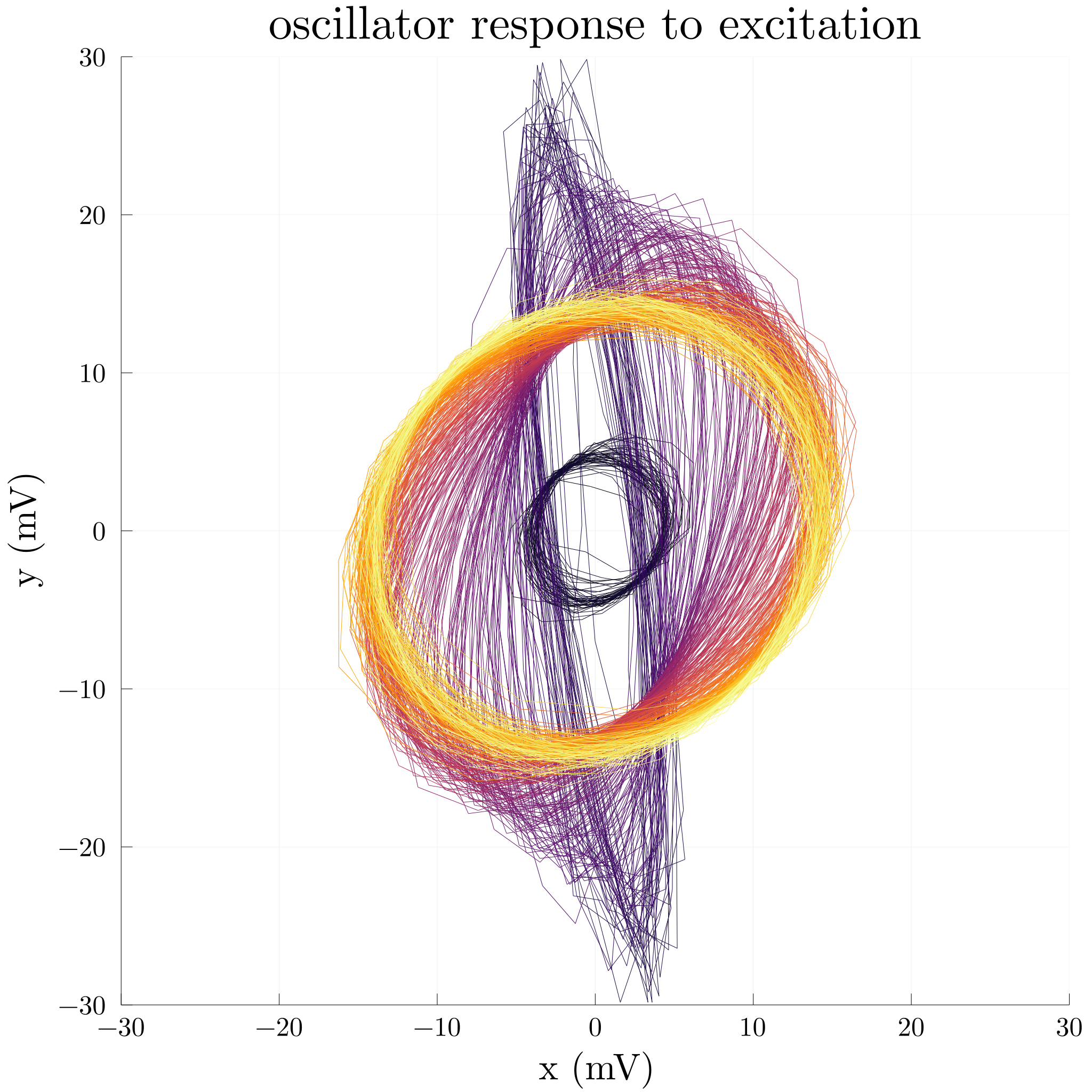
For a simple experiment, we allowed the oscillator to initially hold a small amplitude of around 5 mV (plotted in black), after which I hit it with a small hammer to allow the oscillation to momentarily break away from its circular path (in purple). Below is a plot of the oscillation in the xy plane. You can see that it very quickly decays back to a circular normal mode (in yellow), but with more energy than it initially had, due to the hammer strike.

If you are interested, my original research poster is below (though it mostly re-articulates much of what I have said already):
That’s where we’re at for now. If you have any questions about this project, feel free to contact me through the email listed on the lower left of the poster above!